Testing electrics and electronics
Tracking down and rectifying electrical problems with your battery, starter motor, ignition and lighting. It's actually quite easy to do - you just need a multimeter and the right instructions.
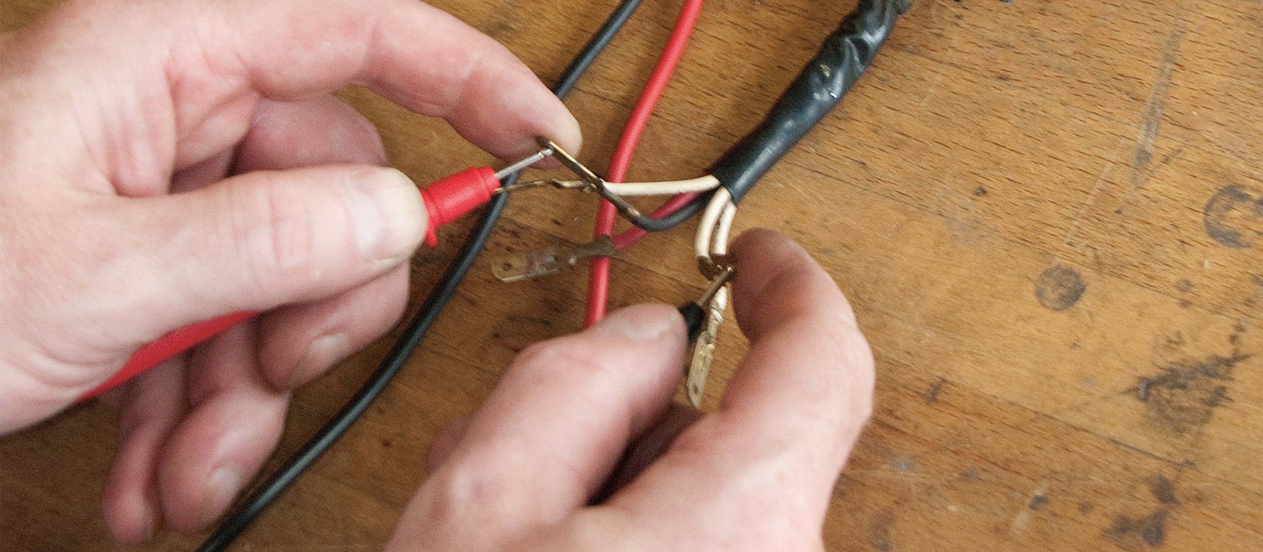
- Testing motorbike electrics
- Checking the charging circuit – now let's get started
- 01 – Charging voltage
- 02 – Testing the alternator
- Checking an alternator with permanent magnet rotor
- Testing non-rectified charging voltage
- Check for continuity and short-circuit to earth
- Check for continuity
- Testing the regulator/rectifier
- Testing a commutator generator
- Checking the ignition circuit of a battery – now let's get started
- 01 – Ignition coils, spark plug connectors, spark plug cables, spark plugs
- 02 – Ignition box
- Testing the starter circuit – now let's get started
- 01 – Starter relay
- 02 – Starter
- Testing the cable harness, switches, etc. – now let's get started
- 01 – Switches, plugs, ignition locks, wiring harnesses
- 02 – Leakage currents
- Earthing faults
- Bonus tips for real DIY mechanics
Testing motorbike electrics
If your electric starter is sluggish, if that vital ignition spark goes missing, headlamps only manage a glimmer, or fuses are blowing by the minute, it's a bit of an emergency for any biker. While mechanical faults can usually be located fairly quickly, electrical faults can be a lot trickier to track down, and often quietly put your whole bike out of action. But with a little patience, a (not at all expensive) multimeter and a few instructions, even a biker with no special training in motorcycle electrics can track down such faults and save an expensive visit to a workshop.
The vast majority of motorbikes (apart from a few enduro bikes and older scooters or mopeds) draw the power for ignition, lights, starter and various other functions from the battery. If the battery packs up, these bikes are off the road.
A flat battery can basically have two causes. Either the charging circuit is no longer charging up the battery sufficiently when you ride your bike, or a leakage current or some device or other is draining the battery without you noticing. If there are indications that the alternator is not charging the battery sufficiently (e.g. the starter is struggling, the headlight becomes dimmer while riding, or the battery charge level indicator light comes on), start with a visual inspection of all the accessible components of the charging circuit: The plug-in connections of the alternator and regulator should be secure and clean; the cables must not show any signs of breaks or chafing and no burn marks, and they should be free of corrosion (green-coloured "verdigris"); also the battery terminals must not be corroded (if necessary, scrape clean with the blade of a knife and apply terminal grease); there should be no visible mechanical faults in the alternator and regulator/rectifier.
To test the individual components further, the battery should be in good condition and fully charged. If you identify a fault in one part of the charging circuit, also check all the other components of the circuit for damage.
Checking the charging circuit – now let's get started
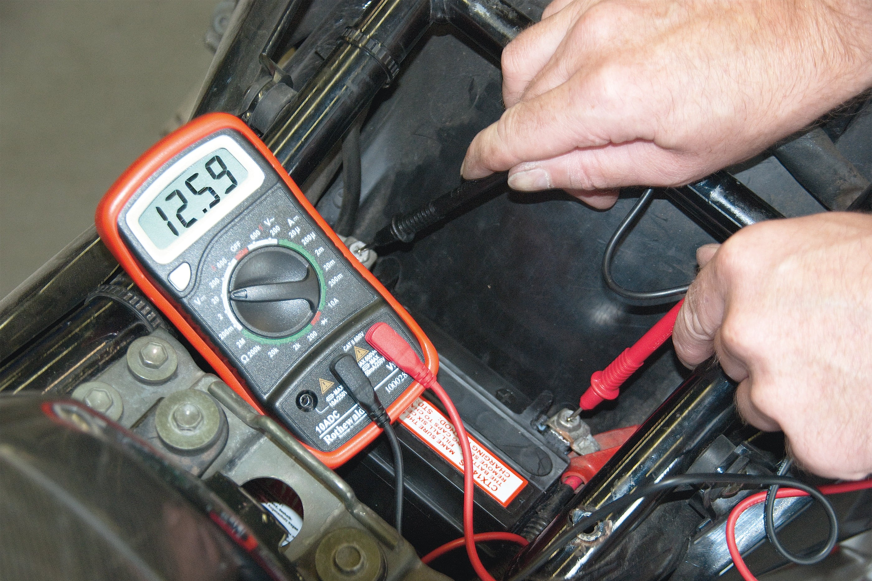
Step 1, Fig. 1: Battery voltage measurement: resting voltage...
01 – Charging voltage
Measuring the charging voltage at the battery is a simple way of revealing whether or not the charging circuit is working correctly. Place the motorcycle (preferably warmed up) on the stand and gain access to the battery terminals. For a 12 V electrical system, adjust your multimeter to the 20 V DC voltage measuring range and connect it to the positive and negative terminals of the battery.
A battery in good condition should have a resting voltage of 12.5–12.8 V. Start the engine and crank it up to approx. 3,000–4,000 rpm. If the charging circuit is working, the voltage should increase up to a certain threshold, but not exceed it.
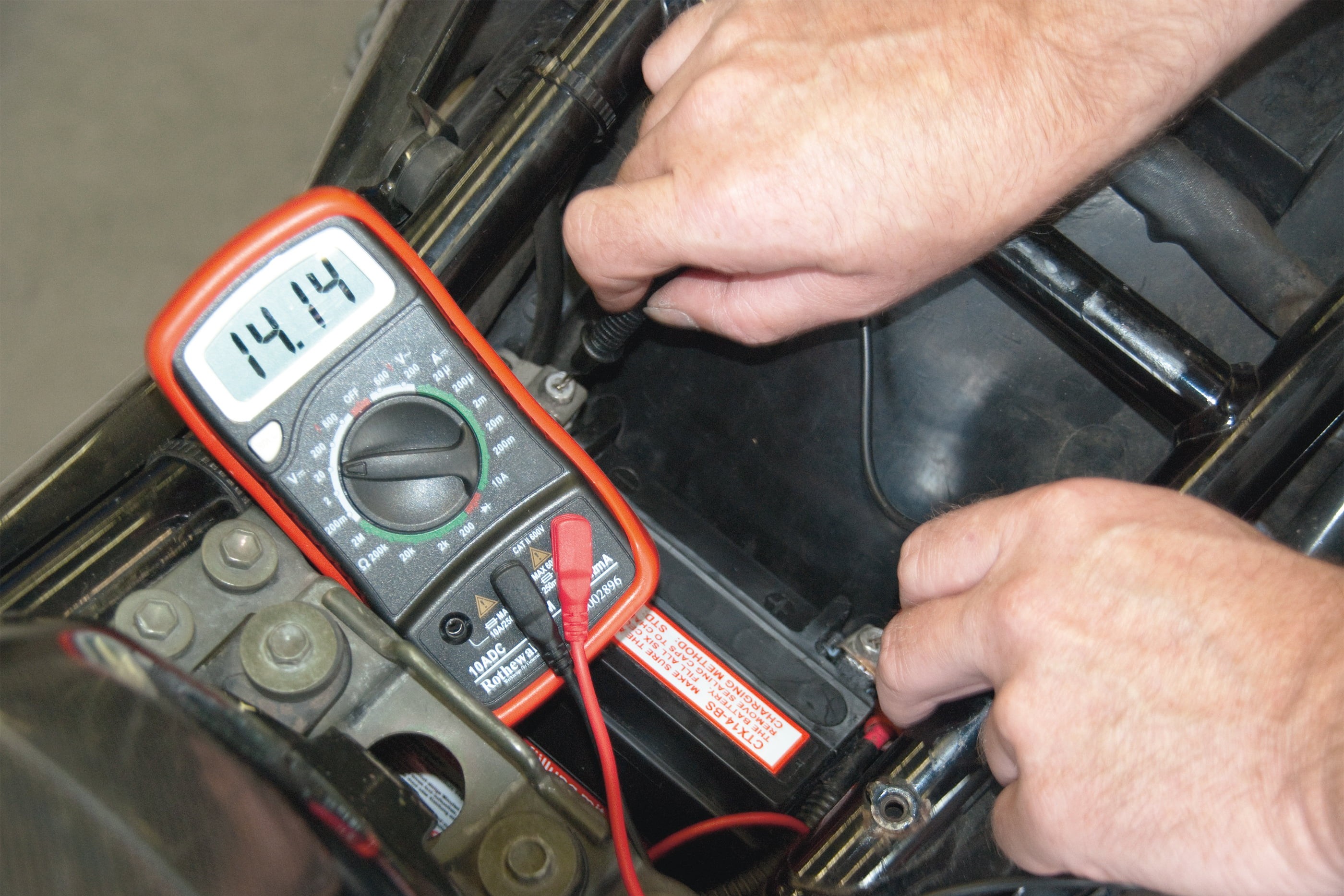
Step 1, Fig. 2: ... limit reached but not exceeded when engine is revved.
Depending on the motorcycle, this threshold can be from 13.5 V to almost 15 V – please refer to the workshop manual for your particular bike model for the exact figure. A reading above the threshold means the voltage regulator (which often forms a single unit along with the rectifier) is faulty and is no longer regulating the charging voltage. This results in acid leakage from the battery and will damage it in the long term due to overcharging.
Measurable short-term voltage peaks indicate a fault in the rectifier and/or alternator. If the voltage does not rise in spite of increasing the revs, the alternator may not be supplying an adequate charging current – so it must be checked next.
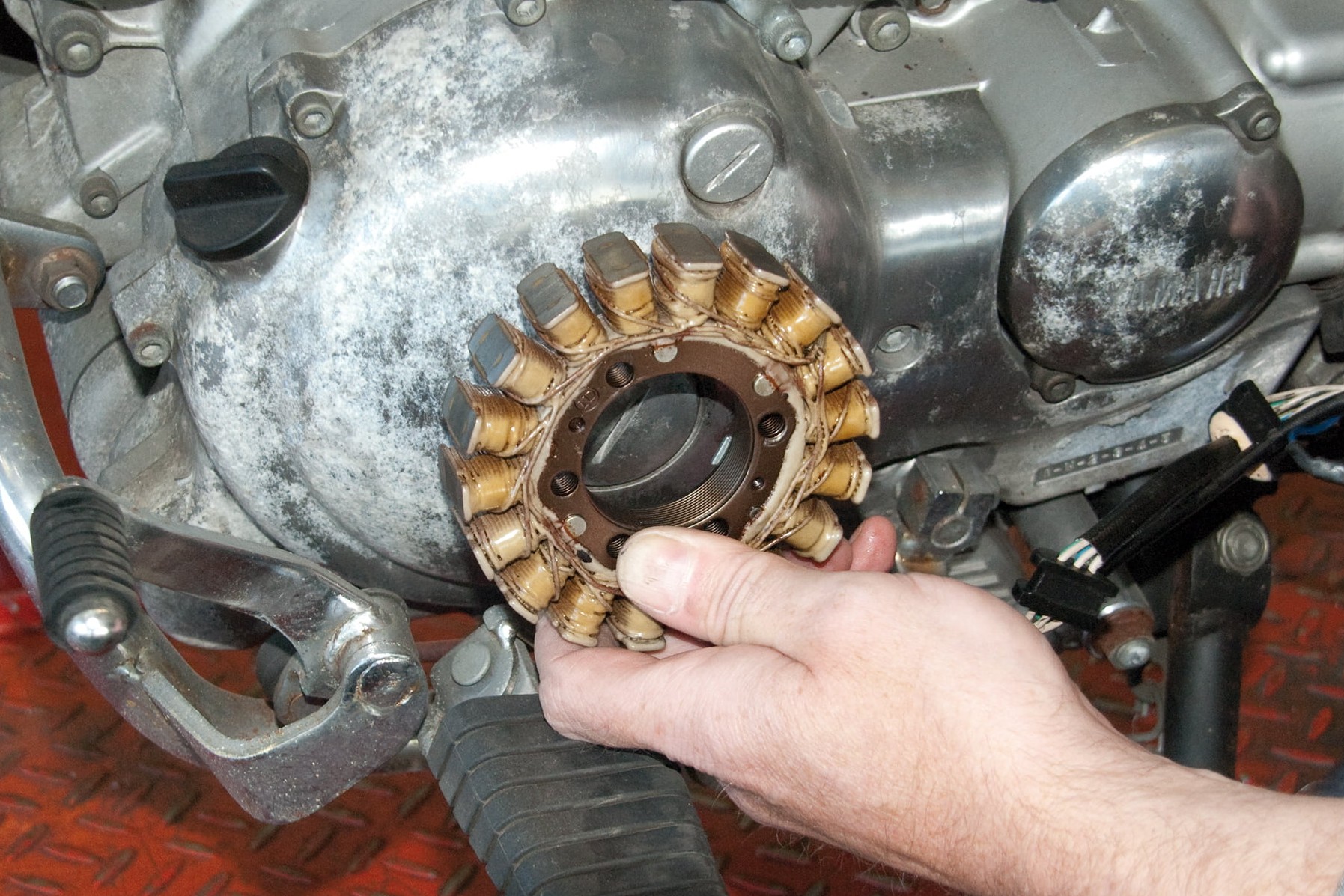
Step 2, Fig. 1: Stator of a 3-phase alternator
02 – Testing the alternator
First find out what kind of an alternator your motorcycle has and carry out the appropriate tests from the list below:
Checking an alternator with permanent magnet rotor
Three-phase alternators operate with a permanent magnet rotor whose rotation induces a voltage in the windings of the outer stator. They run in an oil bath, usually on the crankpin. Faults generally occur as a result of persistent overheating or overloading of the regulator.
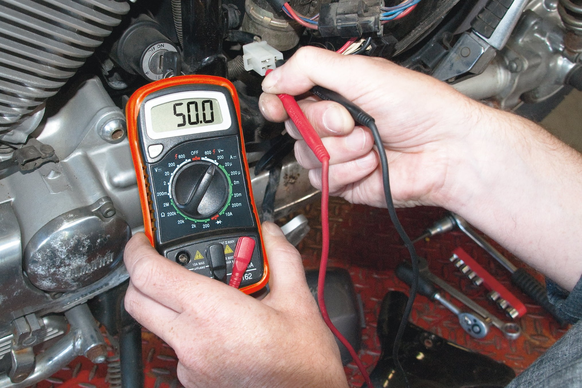
Step 2, Fig. 2: Measure non-rectified charging voltage...
Testing non-rectified charging voltage
Switch the engine and the ignition off. Disconnect the alternator wiring harness from the regulator/rectifier. Now measure the voltage at the alternator itself (preselect measuring range up to 200 V AC).
Connect two of the alternator's plug contacts to the test probes of your multimeter. Run the engine at approx. 3,000–4,000 rpm.
Measure the voltage, turn off the engine, connect the test probes in a second combination, take another measurement with the engine running, etc. until you have checked all combinations. If the measurements are the same (the average motorcycle alternator supplies approx. 50 V–70 V; refer to the repair manual for your model for the exact figures), your alternator is OK. If some of the measured values are significantly below the others, the alternator is faulty.
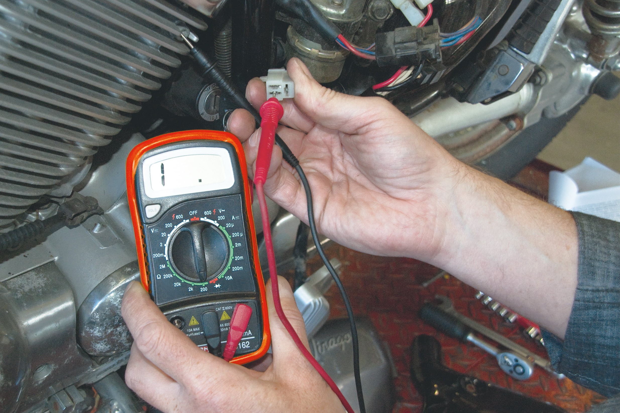
Step 2, Fig. 3: Test stator for shorting to earth (infinite resistance)...
Check for continuity and short-circuit to earth
If the alternator is not supplying an adequate charging voltage, the cause may be a break in the winding or a winding short-circuit to earth. You establish this by measuring the resistance. First, switch the engine and the ignition off. Set your multimeter to resistance measurement in the 200 ohm range. Hold the black test probe against earth and the red probe against each alternator plug contact in turn. There must be no measurable continuity (infinite resistance), otherwise the stator would have a short-circuit to earth.
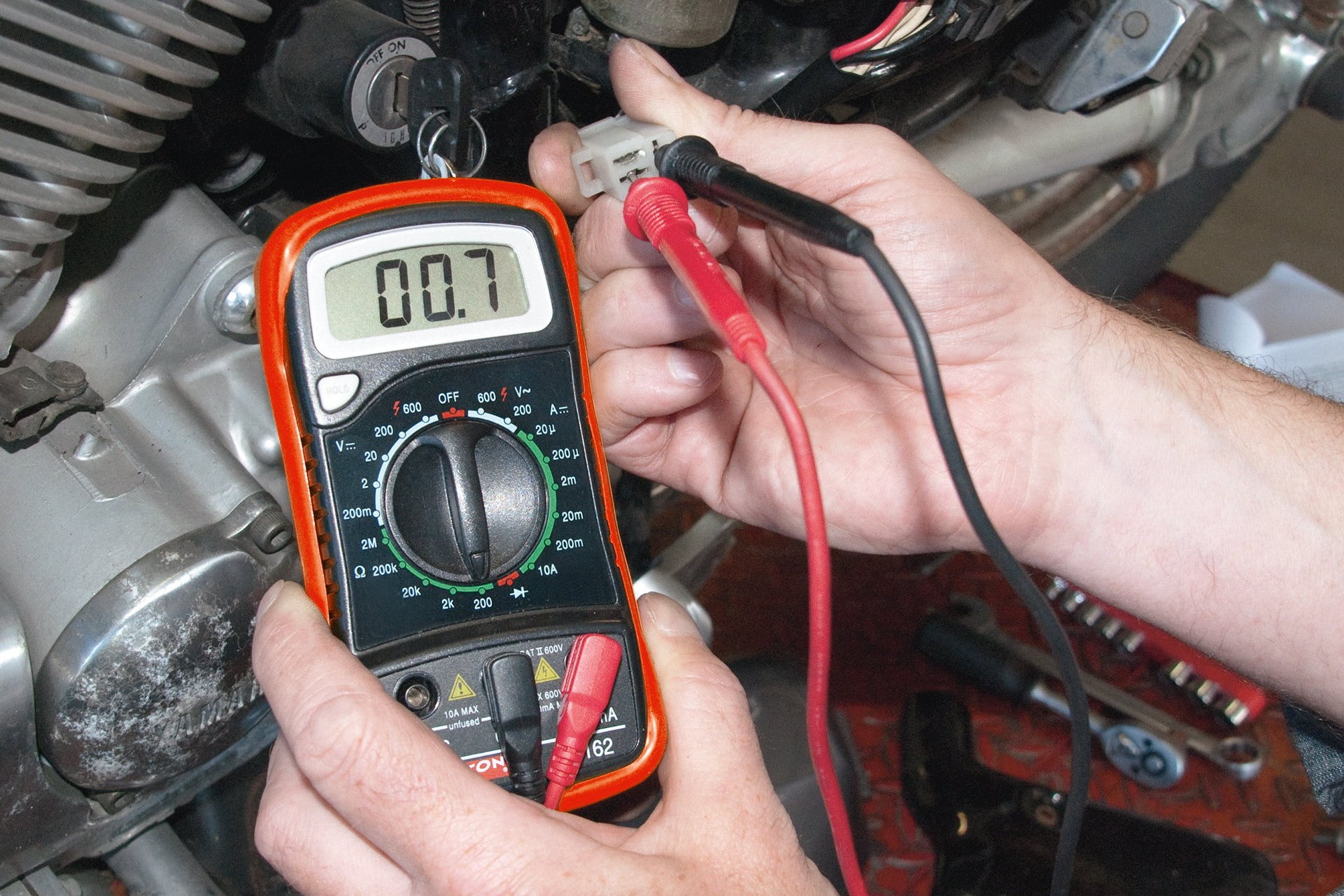
Step 2, Fig. 4: ... and check for continuity
Check for continuity
Next use the test probes to check all the possible contact-to-contact combinations. You should always get a uniformly low resistance (generally less than 1 ohm – please refer to the repair manual for your motorcycle model for the exact figure).
If the measured value is too high, this indicates insufficient continuity between the windings, while a measured value of 0 would indicate a short-circuit. In both cases the stator would be faulty. If the AC voltage at the alternator is considerably too low despite the fact that the alternator windings are undamaged, it can be assumed that the rotor is demagnetised.
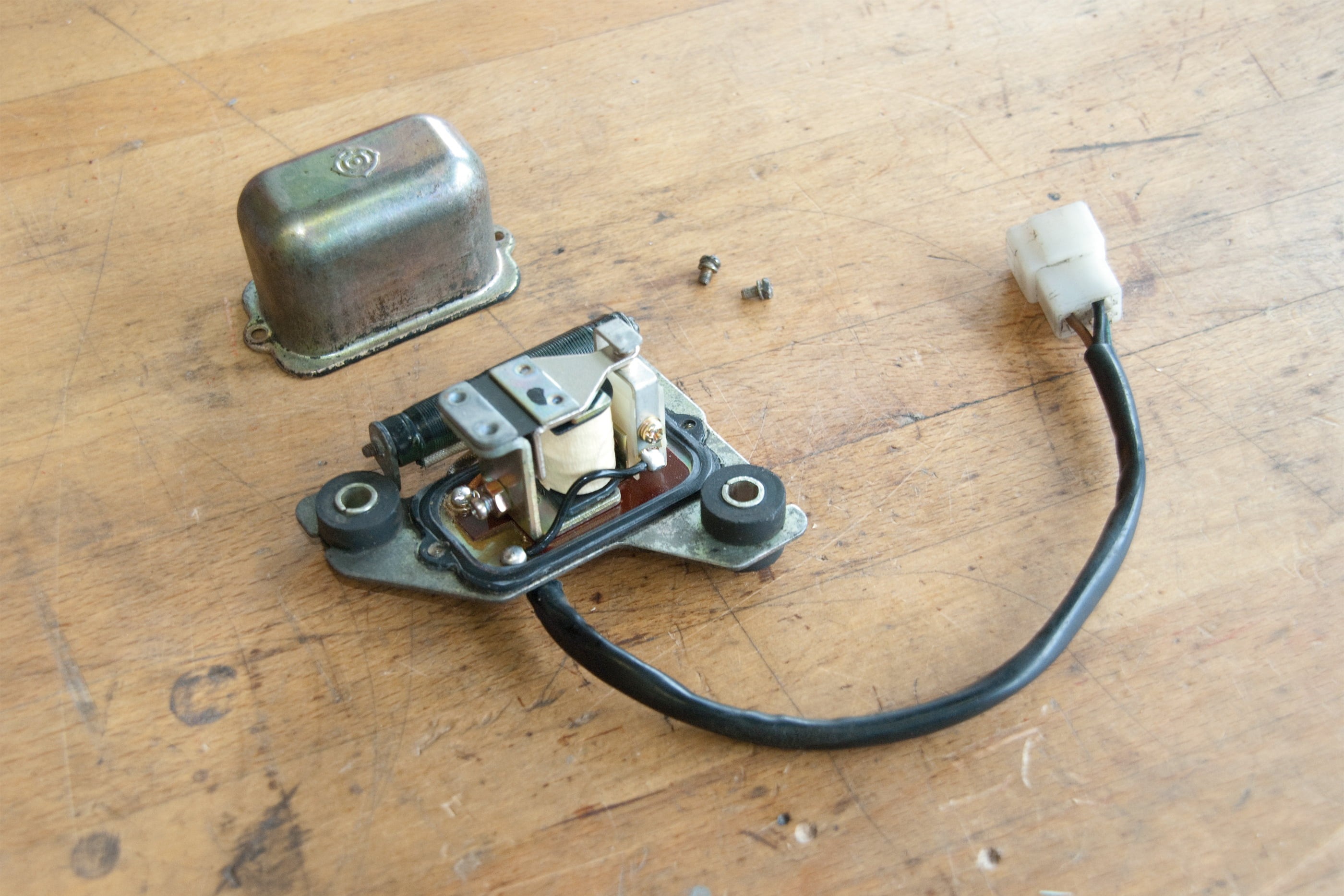
Step 2, Fig. 5: Old, adjustable voltage regulator
Testing the regulator/rectifier
If, on increasing the engine rpm, the voltage measured at the battery exceeds the threshold given by the manufacturer for your motorbike (depending on the model, between 13.5 V and 15 V), the voltage regulator is either faulty (see Step 1) or must be readjusted.
Only vintage and classic motorbikes still have such adjustable regulators – readjustment is also called for here if the battery is not charging properly despite good non-rectified voltage values.
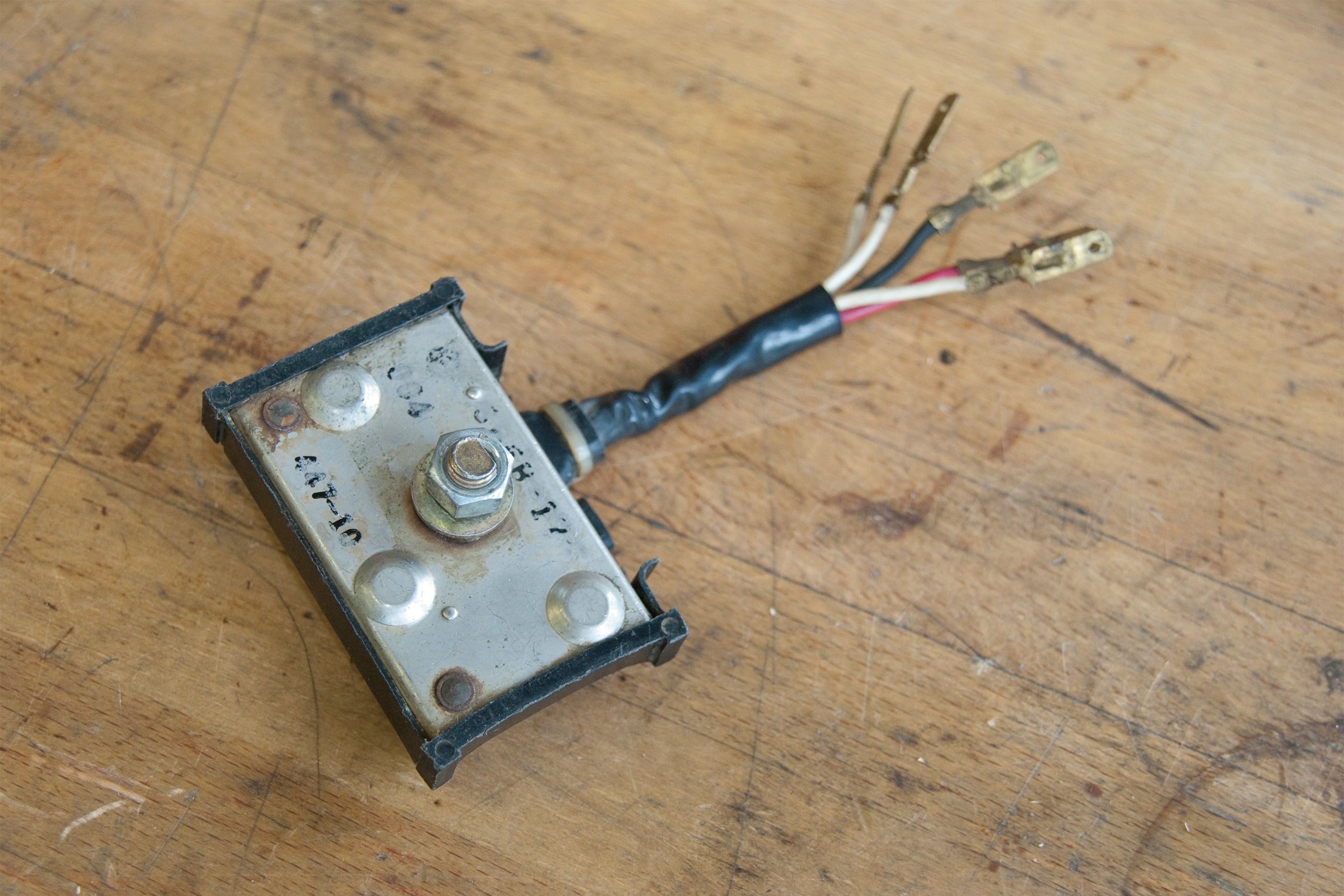
Step 2, Fig. 6: Separate rectifier
To test a separate rectifier, disconnect it from its circuit. Set the multimeter to resistance measurement, and select the 200 ohm measuring range. Now the resistance between the rectifier's earth cable and all the alternator connections, and also between the positive output cable and all connections, must be measured in both directions (in other words reverse the polarity once in each case).
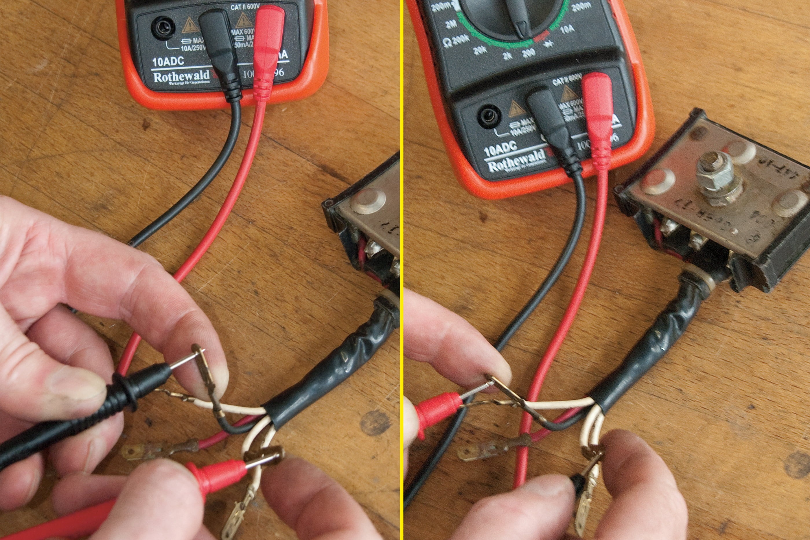
Step 2, Fig. 7: Resistance measurement on rectifier in both directions.
One direction should produce a low reading, while the other direction should produce a reading at least 10 times higher (see Fig. 7). If any of these connections produces the same value in both directions (i.e. despite reversing the polarity), this indicates that the rectifier is faulty and must be replaced.
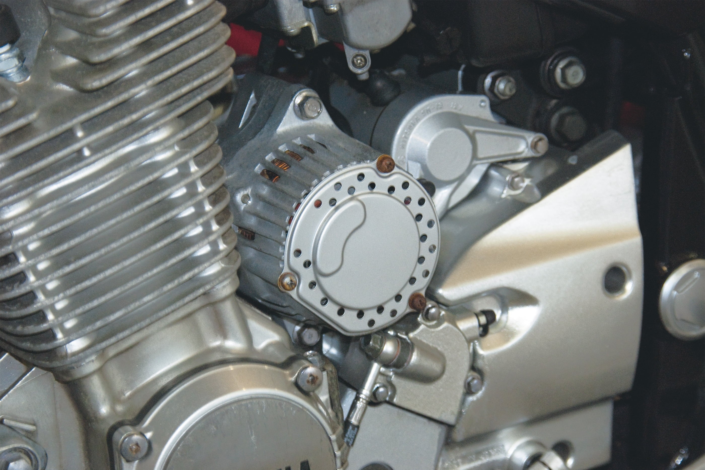
Step 2, Fig. 8: Separate commutator generator
Testing a commutator generator
Commutator generators do not use permanent magnets to induce current; instead they use the electromagnetic energy from an external field winding. The current is picked up by carbon brushes at the rotor commutator. This type of generator always runs "dry", either on the crankshaft stump with an external regulator, or as a separate unit, in which case it will usually have an integrated regulator. Faults are generally caused by vibrations, by shaking due to the rotor's transverse acceleration, or by thermal stresses. The carbon brushes and commutator are subject to long-term wear.
If you intend to test your separate commutator generator thoroughly, it is advisable to remove it from the bike (first disconnect the battery) and then dismantle it.
Inadequate alternator power may, for instance, be due to commutator wear. For this reason, first test the contact pressure of the brush springs and the length of the carbon brushes (change any worn parts). Clean the commutator with petroleum ether or brake cleaner (must be free of grease); if necessary, go over it gently with fine sandpaper (glass paper). The depth of the commutator grooves should be approx. 0.5–1 mm – recut them with a sawblade if necessary or replace the rotor if the slip ring has reached its limit of wear.
To check the stator winding for short-circuit to earth and continuity, set the multimeter to resistance measurement in the 200 ohm range. Now hold one test probe to the front and one to the back of a field winding – you should get a low resistance (less than 1 ohm – for the exact figure, please refer to the repair manual for your model). If the resistance is too high, there is an open circuit. To test for short-circuit to earth, select the high ohm range. Hold the red test probe against the stator winding and the black probe against the housing (earth). The measurement must show infinite resistance, otherwise there is a short to earth (fault). Now measure the resistances between all the commutator bars of the rotor, two at a time (measuring range: again 200 ohms). You should always get a low resistance (frequently in the 24 ohm range – please refer to the repair manual for your model for the exact value); if it is zero, there is a short circuit; if it is too high, there is an interruption, and the rotor must be replaced.
To test for short-circuit to earth, again select the high ohm measuring range. Hold the red test probe against each commutator bar in turn and the black probe against the axle (earth). The measurement must show infinite resistance in each case, otherwise there is a short to earth (rotor fault).
Commutator generators mounted on the crankshaft stump do not need to be removed for testing. You only need to disconnect the battery and remove the generator cover to check the commutator, rotor and stator.
The commutator does not have any grooves. Low alternator power can be due to an oily commutator, worn carbon brushes or faulty pressure springs. There should be no engine oil and no rainwater in the alternator chamber (replace seals as required). Check the stator windings for continuity or short-circuit to earth at the relevant cable connections as described above. Test the rotor windings directly between the two copper tracks of the commutator (as described). You should get a low resistance (approx. 2–6 ohms – please refer to the repair manual for your model for the exact figures). If it is zero, there is a short circuit; if it is high, there is a break in the winding. The resistance measured to earth, on the other hand, must be infinite.
Testing the regulator/rectifier: as described in Step 2.
If it turns out that the alternator is faulty, you must decide whether getting it repaired by a specialist firm is worthwhile, or whether to buy an expensive OEM replacement, or possibly source a functional/tested used alternator with warranty from a supplier – in any case, it pays to compare prices.
Checking the ignition circuit of a battery – now let's get started
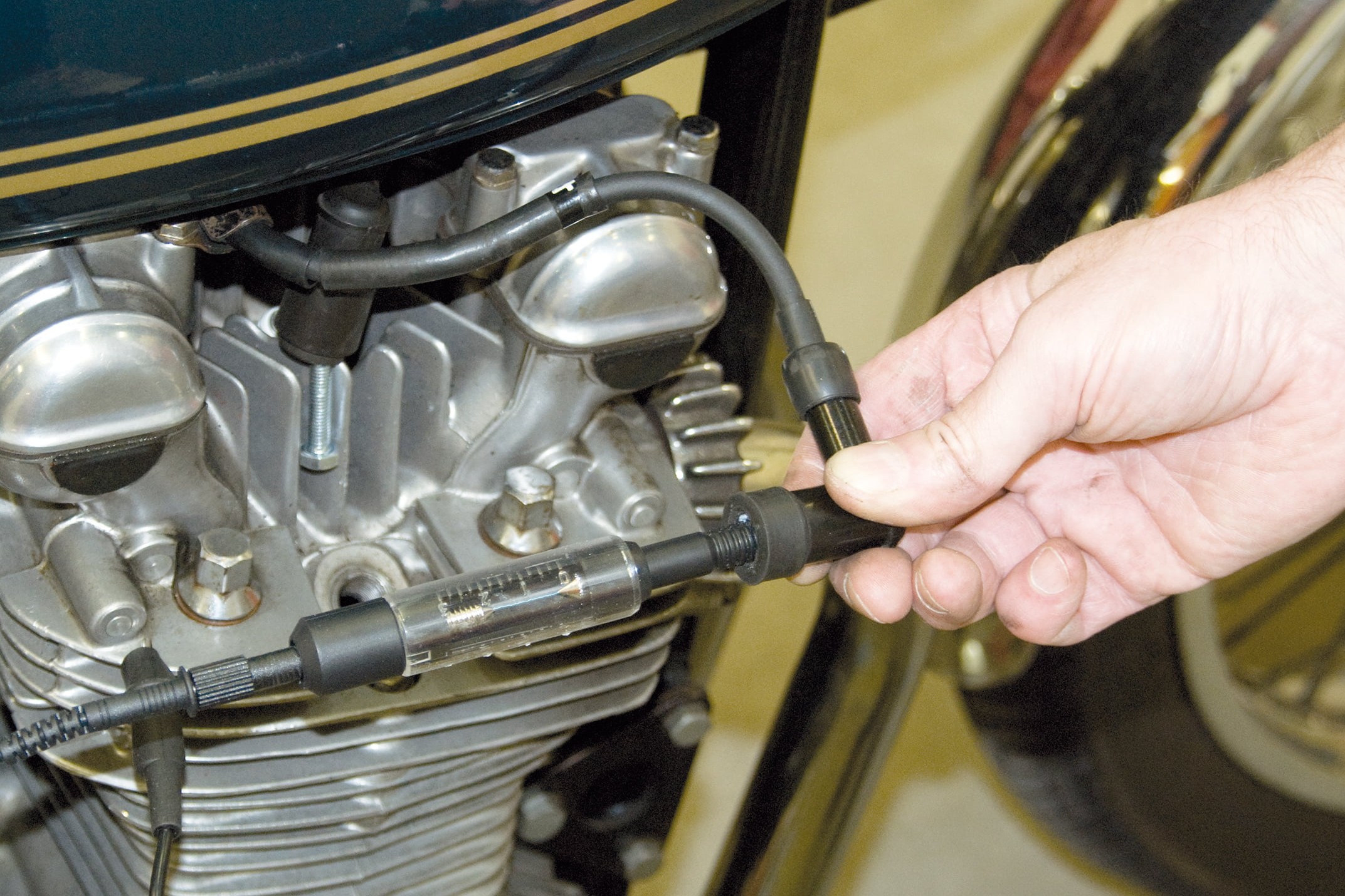
Step 1: Test the ignition voltage
01 – Ignition coils, spark plug connectors, spark plug cables, spark plugs
If your bike refuses to start even though the starter is cranking the engine and the correct air/fuel mixture is getting to the engine (spark plug is getting wet), the cause is a fault in the ignition circuit. If the ignition spark is weak or non-existent, first visually inspect the cable connections, spark plugs and spark plug connectors. It is best to change ageing spark plugs, connectors and cables there and then. Using iridium spark plugs improves starting (better self-cleaning, stronger ignition spark). If thin, burned looking streaks can be seen on the ignition coil housing, these could be current creepage paths caused by dirt or material fatigue of the coil body (clean or replace).
Moisture, too, can get into the ignition coil through hairline cracks, and cause short-circuits. Older ignition coils frequently cease to function after the engine has warmed up, and work again after it has cooled down – here again, the only solution is to replace them.
To check the quality of the ignition spark, you can check the spark gap with a spark gap tester.
A spark of sufficient strength should be able to jump a gap of at least 5–7 mm from the spark plug cable to earth (the spark from a really good coil will jump 10 mm and more). It is not advisable to let the spark jump to the engine block without a spark gap tester, as this may damage the ignition box and you could easily get an electric shock if you are holding the cable in your hand.
A weak ignition spark may also be due to a voltage drop in the ignition circuit (especially in older bikes, e.g. due to corroded cables: to check, see below). If in doubt, it's best to leave checking the ignition coil itself to a motorcycle workshop.
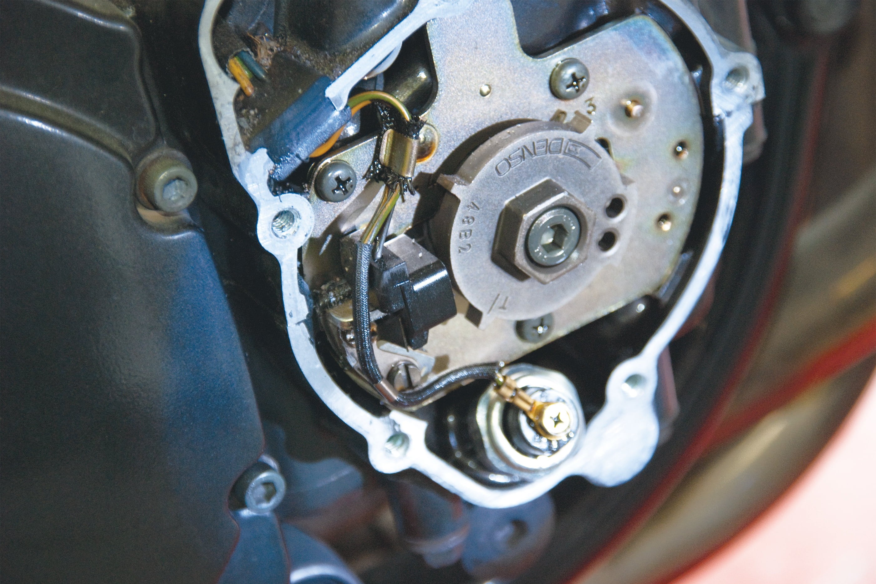
Step 2: Ignition box pick-up
02 – Ignition box
If the spark plugs, spark plug connectors, ignition coils and cable connections are all in good condition and you still get no ignition spark, there is a fault in the ignition box or its controller (see below). The ignition box itself is a sensitive and, unfortunately, expensive component, so it should only be checked by a motorcycle workshop with a special tester. The only thing you can check yourself is whether the cable connections are in perfect condition.
Electronic ignition systems receive their pulse from a rotor finger that is usually attached to a crankpin and activates a pulse generator coil ("pick-up"). You can check a pick-up yourself with the multimeter.
To do so, set it to resistance measurement in the 2 kilohm range. Disconnect the pick-up, hold the test probes against the connections and compare the measurement with the workshop manual for your bike model. A resistance that is too high indicates a line break, while one that is too low indicates a short circuit. Now adjust the multimeter to the 2 megohms range and measure the resistance between the winding and earth – if it is not "infinite", there is a short to earth and the coil must be replaced.
Testing the starter circuit – now let's get started
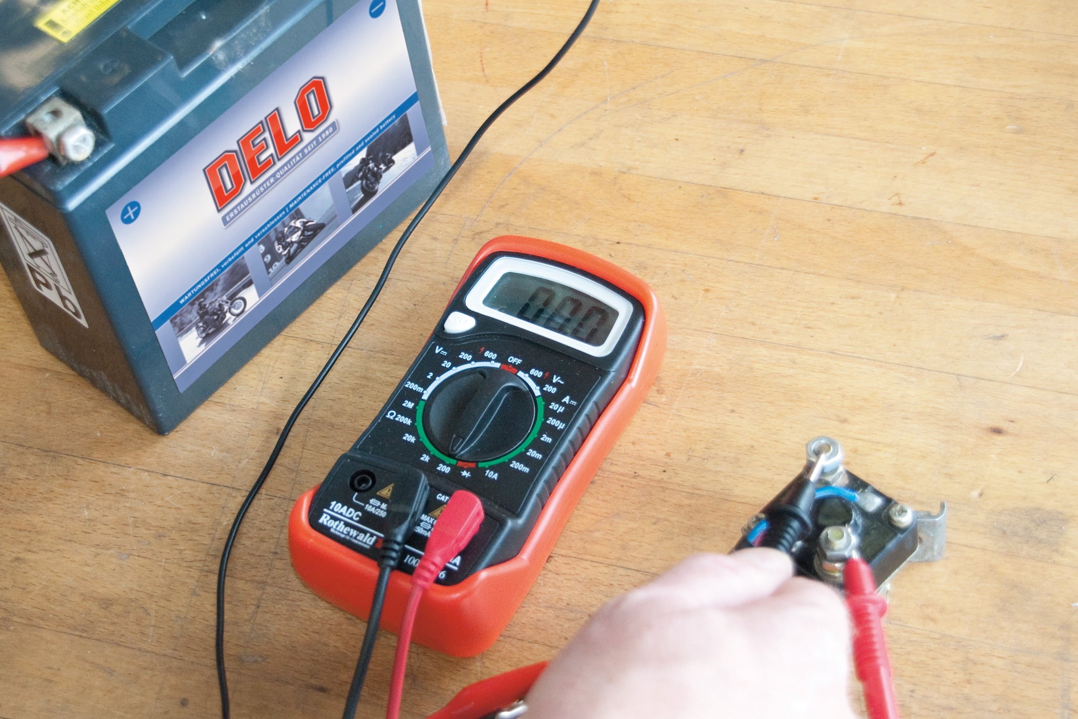
Step 1: Test starter relay for continuity.
01 – Starter relay
If all you hear when trying to start the engine with a well-charged battery is a clattering or buzzing sound, and the starter motor does not crank the engine, there is probably a fault in the starter relay. The purpose of the starter relay is to reduce load on the cabling and the switch in the starter circuit. To check the relay, the best thing is to take it out. Set the multimeter to resistance measurement (200 ohm measuring range). Connect the test probes to the "thick" battery terminal and the thick terminal of the starter motor. Hold the negative connection of a well-charged 12 V battery to the negative side of the relay (see wiring diagram for the specific bike model); and the positive connection to the positive side of the relay (see wiring diagram – generally the connection to the start button).
The relay should now "click" and a resistance of 0 ohms be measured.
If the resistance is significantly greater than 0 ohms, the relay is probably faulty even if it clicks. If the relay does not click, it must be replaced too. If you can get the reference values from a workshop manual for the specific bike model, you can also measure the internal resistance of the relay. To do so, hold the test probes of the meter to the "thin" terminals of the relay and take the reading.
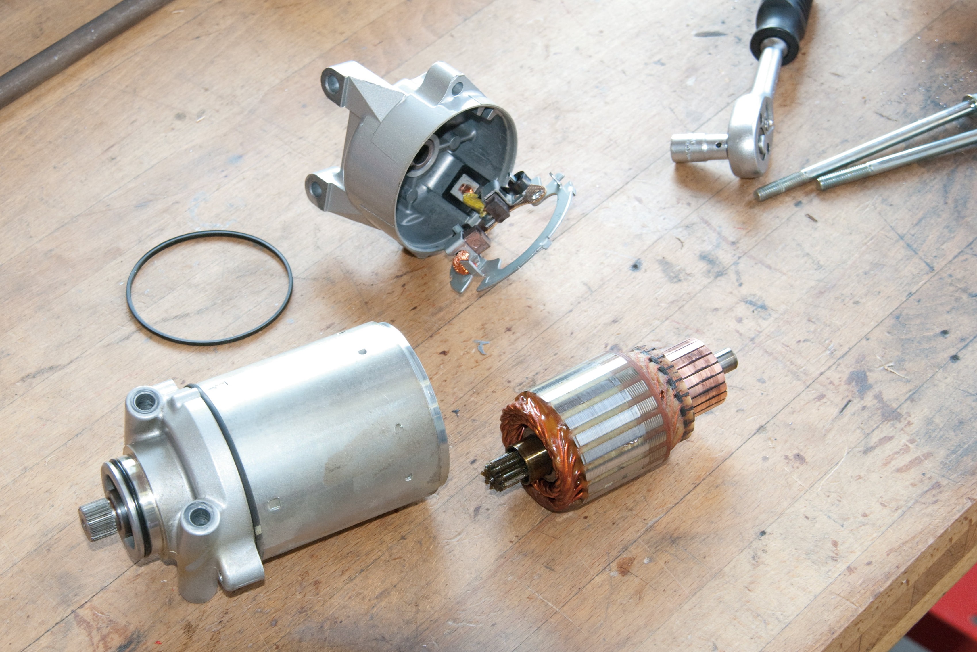
Step 2, Fig. 1: Dismantled starter motor
02 – Starter
If the starter relay is intact but the starter motor does not work even though the battery is well charged, first examine the start button, as corrosion often breaks the contact in older motorbikes. The solution is to clean it with sandpaper and a little contact spray. You can check the start button by measuring the resistance with the multimeter after disconnecting the cable inlets. If the measured value is greater than 0 ohms, this indicates a faulty switch (clean it once more and then measure again).
If you need to check the starter motor itself, the best thing to do is to take it out (disconnect the battery) and dismantle it.
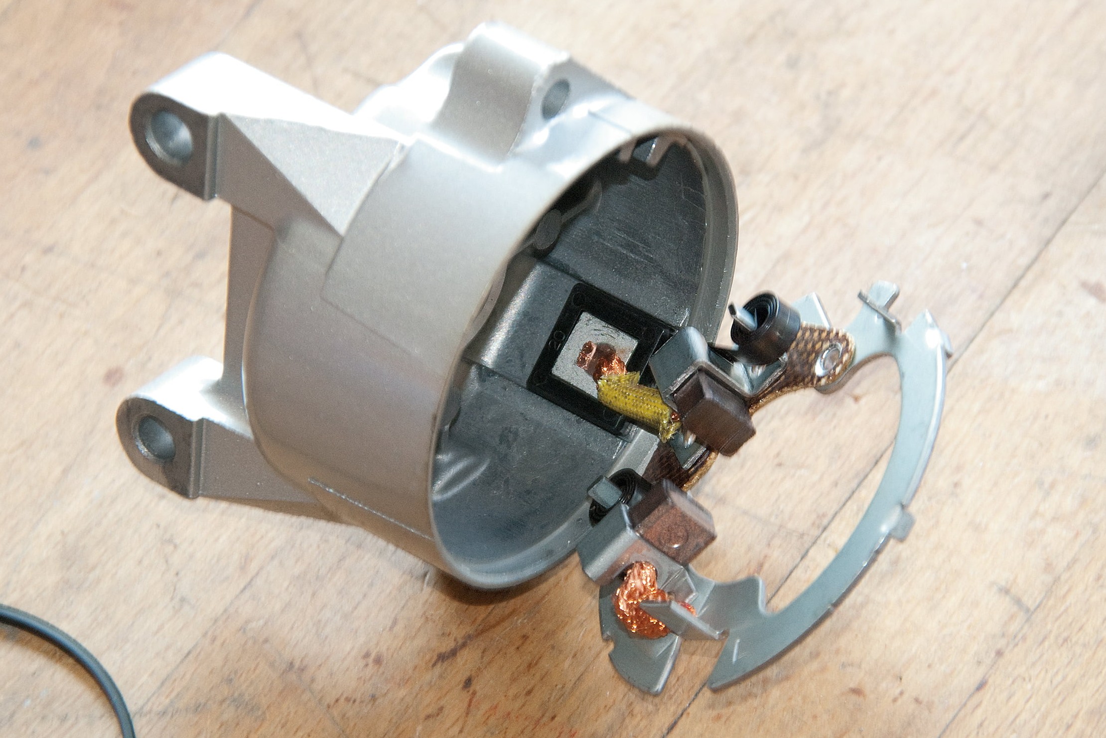
Step 2, Fig. 2: These carbon brushes are OK
First check the contact pressure of the brush springs and the length of the carbon brushes (replace worn carbon brushes). Clean the commutator with petroleum ether or brake cleaner (must be free of grease); if necessary, go over it gently with fine sandpaper (glass paper).
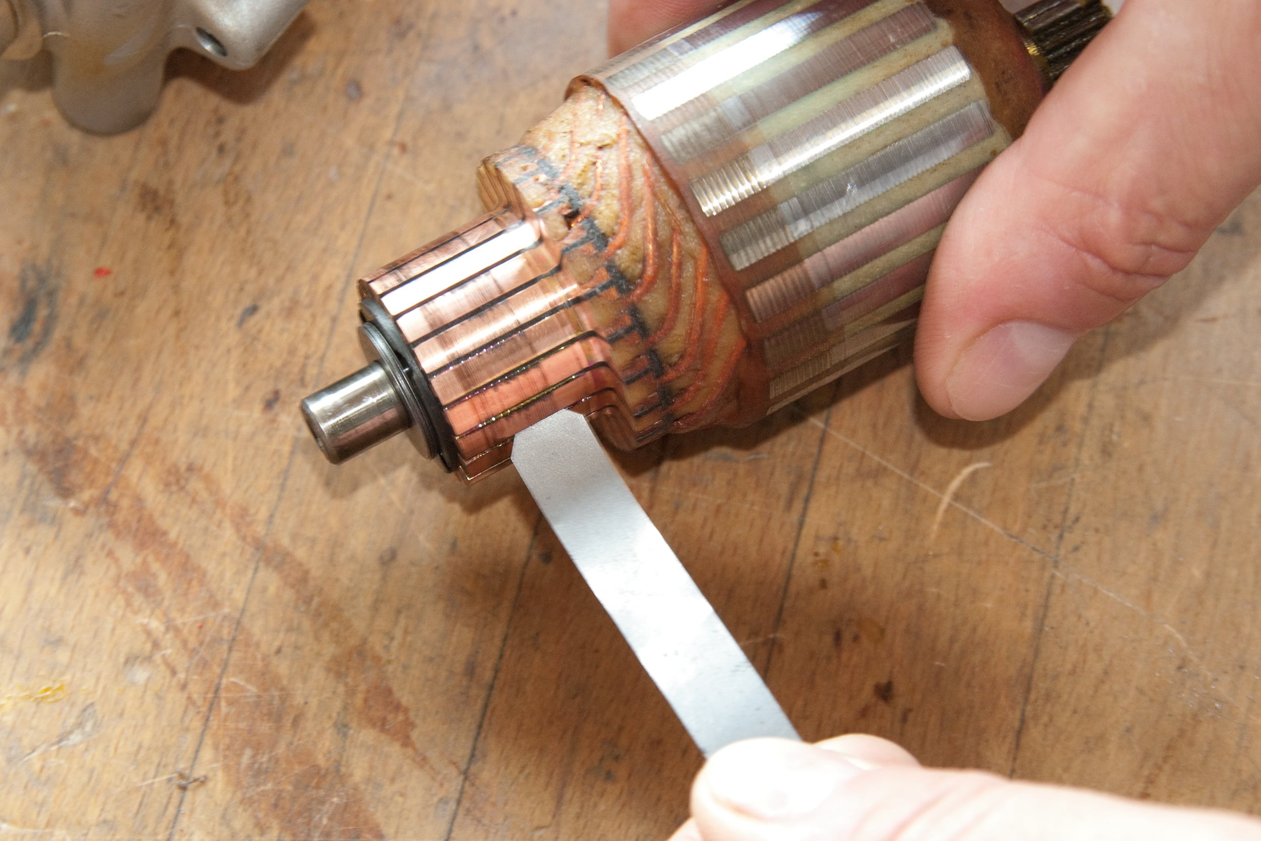
Step 2, Fig. 3: Check depth of commutator grooves
The depth of the commutator grooves should be approx. 0.5–1 mm – recut them if necessary with a thin sawblade (or replace the rotor).
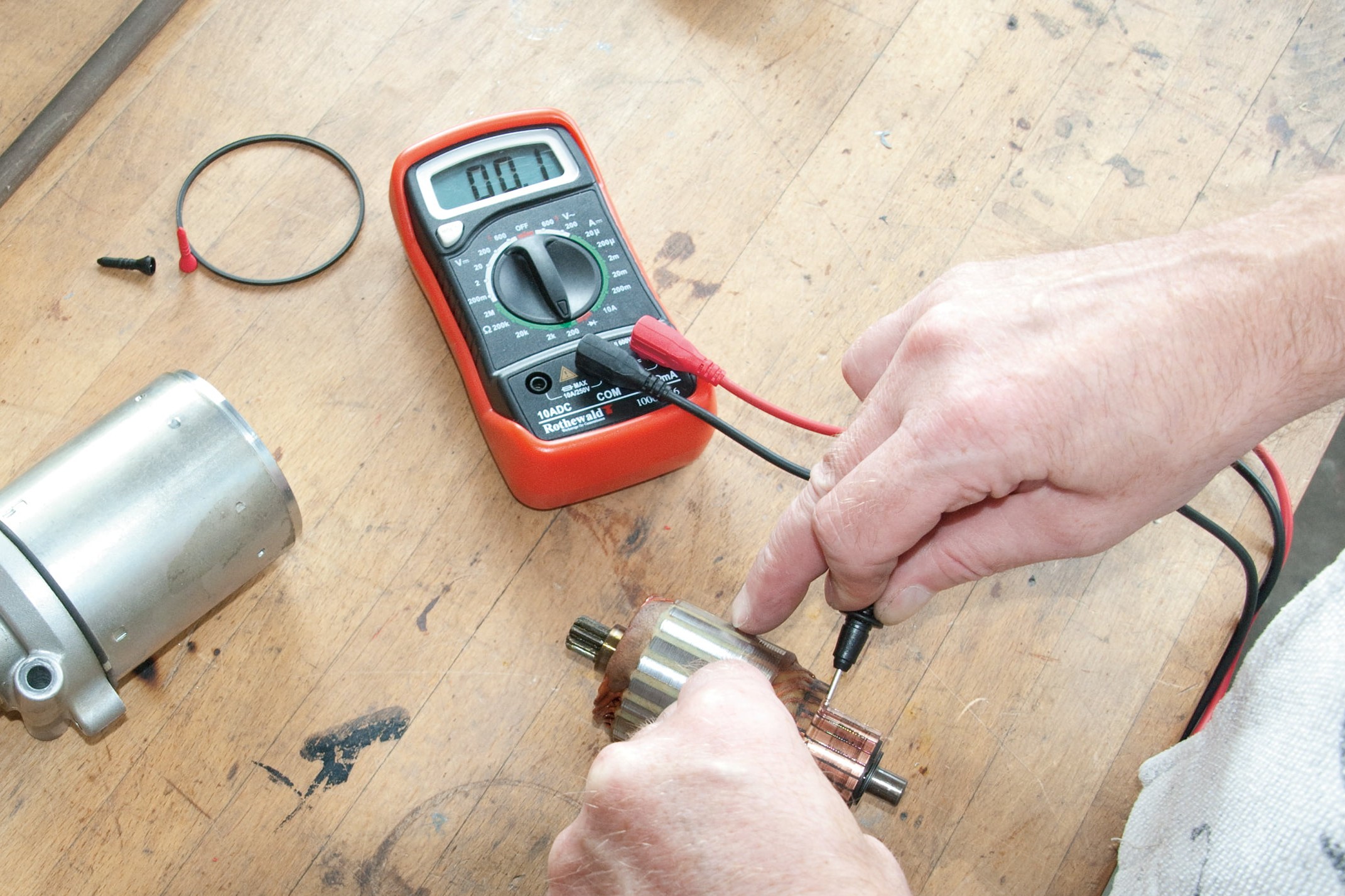
Step 2, Fig. 4: Continuity test between commutator grooves...
To test the rotor for short-circuit to earth and continuity, measure the resistance as described for the alternator. First set your multimeter to the 200 ohm measuring range and measure the resistances between two commutator bars at a time, in all possible combinations.
You should always get a low resistance (less than 1 ohm – please refer to the repair manual for your model for the exact figure).
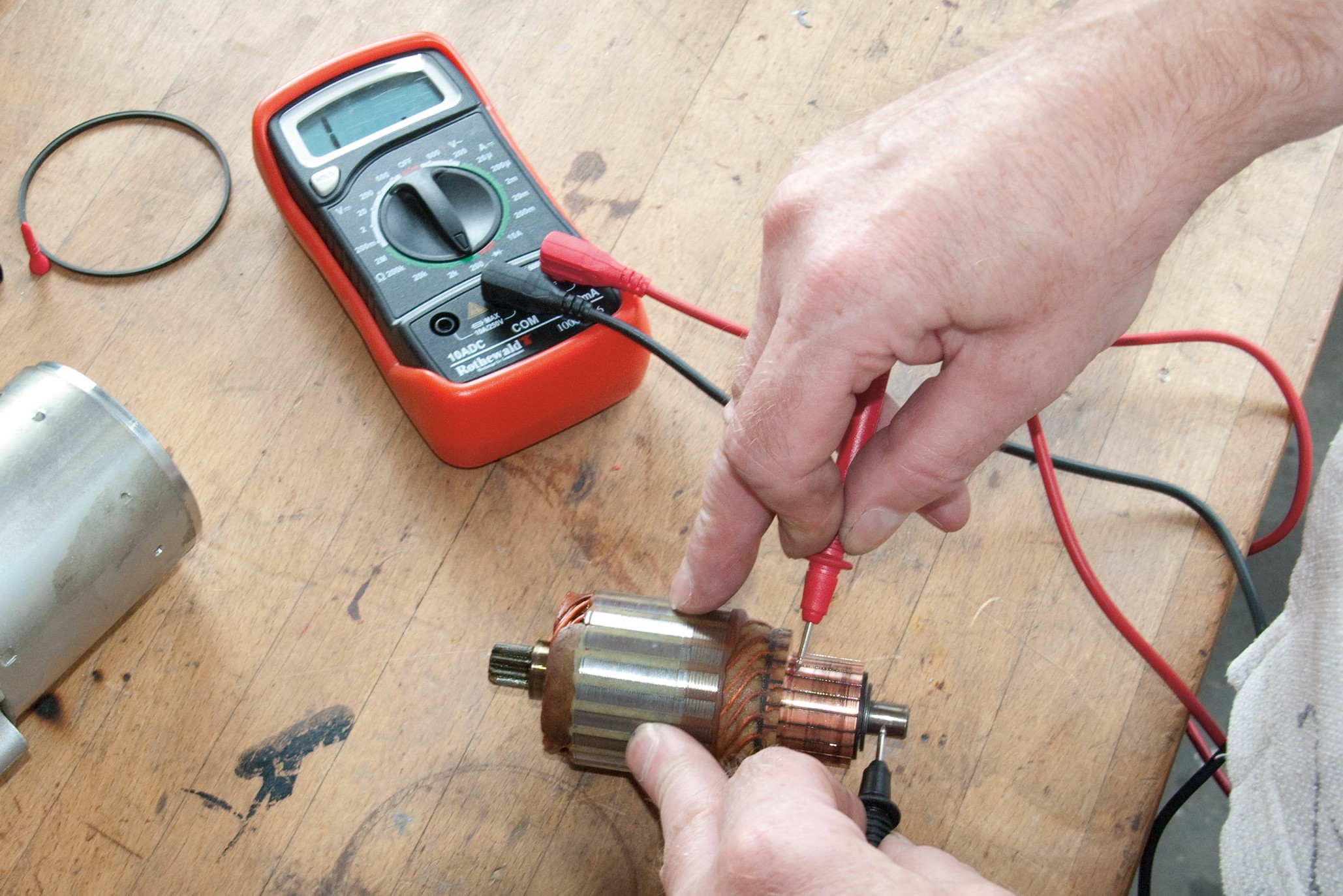
Step 2, Fig. 5: ... and check rotor for shorting to earth
If it is too high, there is an interruption and the rotor is faulty. Now select the measuring range up to 2 megohms on the multimeter. Hold the red test probe against each commutator bar in turn and the black probe against the axle (earth). Unless infinite resistance is measured in each case, there is a short to earth and the rotor is likewise faulty.
If the starter motor stator has field windings instead of permanent magnets, they should likewise be tested for shorts to earth (if the resistance between earth and field winding is not infinite, replace the winding) and for continuity (the resistance in the winding should be small, see above).
Testing the cable harness, switches, etc. – now let's get started
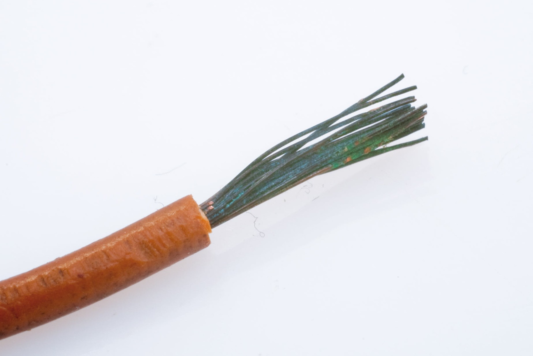
Step 1: Green corrosion on cable cores causes voltage drop
01 – Switches, plugs, ignition locks, wiring harnesses
With the passage of time, corrosion and dirt can build up high contact resistance in plugs and switches; cable harnesses that are affected by copper corrosion make poor conductors. In extreme cases, this can result in a component becoming completely disabled, whilst less serious damage can cause a more or less noticeable reduction in the efficiency of electrical devices such as lights or ignition. A simple visual inspection of components is often all that is required: green connector tabs and corroded switch contacts must be scraped or sanded clean and refitted with a little contact spray. Cables with greenish cores should be replaced. A cable cross-section of 1.5 is generally sufficient on a motorcycle, although slightly thicker cable is used for the main positive lead, while the cable connecting the battery with the starter relay is specially dimensioned, as is the starter cable itself.
Exact information on a cable's conductivity is provided by a resistance measurement. To do this, disconnect the battery, set the multimeter to measuring range 200 ohms, and hold the test probes against the cable inlets of the switch or plug (switch in the ON position). If a resistance greater than approximately 0 ohms is measured, this indicates faults, dirt or corrosion damage.
Measuring the drop in voltage can also provide information on the quality of power supply to a component. This can be done by selecting the measuring range 20 V DC on the multimeter. Disconnect positive and negative leads from the electrical device and hold the black test probe against the negative lead and the red probe against the positive lead. The measurable voltage should be approx. 12.5 volts (that is, as close as possible to the rated battery voltage) – readings below this suggest energy losses.
02 – Leakage currents
If you haven't ridden your bike for a few days and the battery is already completely flat, the culprit is generally either a hidden load somewhere (e.g. a clock running off the electrical system), or leakage current draining your battery. Leakage current may be caused by the ignition, a faulty switch, a relay or a pinched or frayed cable. You can track down leakage current by using a multimeter on the ammeter setting.
Remember that to avoid overheating, your multimeter must never be subjected to loads in excess of 10 A (please refer to the Safety Instructions on www.louis.eu). So on no account use it to measure current on the positive lead to the starter, or on the thick battery cable to the starter relay, or at the alternator.
First switch off the ignition on the bike and take the negative cable off the battery. Select the "milliamps" measuring range on the multimeter. Hold the red test probe against the disconnected negative cable and the black test probe against the negative terminal of the battery. If a current can be measured, this indicates that there is a leakage current.
The source of the leakage current can be narrowed down by removing fuses from the bike one by one. The circuit whose fuse cancels out the reading on the multimeter is the source of the leakage current and must be investigated thoroughly.
Earthing faults
Does your tail light flash dimly when you activate the turn signal? Are your bike's electrical functions not performing optimally? Then your bike probably has an earthing fault. Make sure that the earth lead is always securely connected on the battery (and the positive cable too, of course). Corroded terminals can also lead to contact difficulties – but this is not always obvious to the eye. Scrape clean the darkened lead terminals with a knife. A little terminal grease will help prevent corrosion recurring.
Bonus tips for real DIY mechanics
Misuse of the steering head bearing
The steering head bearing is not intended to be used as an earth connection for various power consumers. Yet on some motorcycles, this is exactly what happens. And even if the bearing is able to fulfil this function, it's not actually a bad idea. A current of 10 amps is easily reached, and the bearings start to crackle, while tiny beads of sweat form on bearing balls and rollers. This leads to increased wear. To avoid the problem, install a small wire between fork and frame. Job done!
... In the middle of a bend, your engine suddenly dies
This can happen if a tilt switch (lean angle sensor) is activated, whose actual purpose is to cut off the engine in the event of an accident. This type of switch is used on various motorbikes. Conversions to these bikes, or incorrect installation, can give rise to serious malfunctions, which can be dangerous. In fact, potentially lethal!
Electrical connectors must be watertight
Unprotected connectors are a seriously bad news. They may do their job perfectly well in dry, sunny biking weather, but it's a different story in rain or damp weather conditions. So it's always best to replace them with waterproof connectors. Then you don't have to worry. Including when you give your bike a thorough washing down.
The Louis Technical Centre
If you have a technical question about your motorbike, please contact our Technical Centre, where they have endless experience, reference books and contacts.
Please note!
These tips for DIY mechanics contain general recommendations that may not apply to all vehicles or all individual components. As local conditions may vary considerably, we are unable to guarantee the correctness of information in these tips for DIY mechanics.
Thank you for your understanding.


