Installing motorcycle instruments
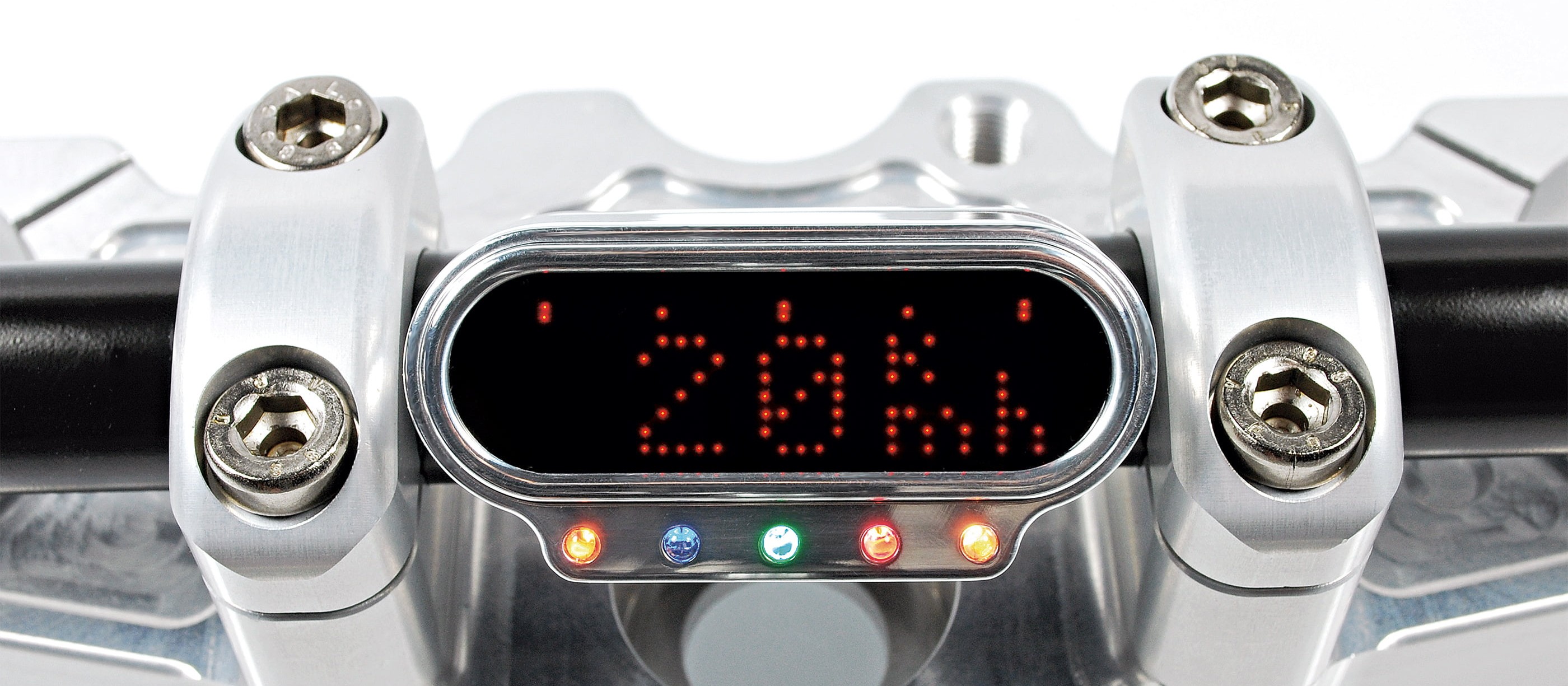
The mandatory equipment for custom bikes includes small, stylish instruments. It is perfectly possible for DIY mechanics to carry out the conversion. We show you how, using motogadget instruments as an example.
Note: The videos are in German.
- Installing motorcycle instruments – now let's get started
- Inductive sensors or proximity sensors on the transmission output
- Reed contact with magnet on wheel
- Retrofitted or additional speed sensors
- Tachometer
- Ignitions with negative input pulse
- Ignitions with positive input pulse
- Differentiating between the types of ignition
- Menu button
- Wiring diagram of electrical connection: Example of motoscope mini
- Final set-up
Preparation of the conversion
Small, stylish and precise: well-designed instruments from motogadget look awesome, especially on custom bikes. Many bikers steer clear of any job that involves the electrical system or electronics. After all, you can't actually see electricity or voltage unless, of course, sparks start flying due to some electrical bug or other. But, in fact, it's not at all difficult to install a well-designed instrument on a naked bike, chopper or streetfighter.
The knowledge you need
If you're planning to work on your bike's electrical system, you should have a good idea about the basics, like current and voltage, positive and negative terminal. Ideally, you should also have a wiring diagram and at least roughly understand it so that you can identify individual components such as the battery, ignition coil, ignition switch, etc., and how they are wired.
Installing motorcycle instruments – now let's get started
If electrical problems arise, a multimeter is useful, in addition to the wiring diagram, specifically to measure the voltage and its polarity, the amperage and resistance. If you do not have a wiring diagram, or if a wiring harness has been modified, you can use the multimeter to identify a particular circuit and its connections quickly. It also enables you to find wiring faults, missing connections, undesirable contact resistances, and so on. In most cases, however, you will be able to connect up an instrument without a multimeter. To cut electric cables, you need a pair of side cutters. To strip them, you use an insulation stripper. Depending on which type of connection you choose, you need to use either a soldering iron plus solder or a crimping tool and suitable crimp contacts. Crimping pliers often cut and strip as well. motogadget instruments always come with a push-fit connection with crimp contacts or cable terminals for connecting the instrument to the wiring harness. You should have things like heat shrink tubing, insulating tape, cable ties and additional lengths of cable (with a suitable diameter) at the ready in case you need to extend a cable. Additional plug-in connectors with crimp contacts may be used optionally.
Depending on the motorcycle and where you are installing the instruments and sensors, universal motogadget mounts or self-made mounts may be used. To make a mount yourself – e.g. designed to fit the top triple tree of your bike – first make a cardboard template on the bike itself and then transfer it to an aluminium plate. To adapt and install a ready-made mount, you usually need a metal-cutting saw and some metal files along with sandpaper. The fastening holes can be drilled with a handheld or bench power drill. It is highly recommended that you first decide the fastening points and measure them out with a tape measure or caliper gauge and mark them using a square and marker pen or scriber. Depending on what fastening you choose, you normally need a set of hexagon keys and a set of open-end wrenches. What you will also need for fastening the mounts to the bike is suitable nuts, bolts and washers. motogadget supplies bolts for fastening the instrument to the universal mounts. If you have to fasten the speed sensor to the front or rear wheel, you should have a suitable piece of sheet aluminium or stainless steel.
People often ask whether modern electronic instruments can be used on older motorbikes. The answer is a resounding "yes", and the "how" is answered next.
The power supply for most of the instruments from motogadget should be between 7 V and 18 V. Therefore, the normal electrical system of approx. 12 V will always be sufficient. In most cases only "switched positive" on the electrical system is required. This means that the power is switched on and off via the ignition (terminal 15). Certain instruments, such as the "motoscope tiny", additionally require connection to the permanent positive terminal of the battery. Important: Before you connect anything, you should always completely disconnect the battery from the electrical system. We recommend the additional use of an inline fuse for the instrument (included).
To measure the motorbike's speed, an electrical pulse is required whose clocking/frequency is proportional to the speed. Electronic sensors on the front wheel, rear wheel or transmission output are used for this.
Most modern motorbikes are fitted with electronic speed sensors. 3 different sensor types are used:
Hall sensor on wheel or transmission output – These are not compatible with motogadget instruments, as the signal voltage is relatively low (well below 5 V). Instead, the speed sensor included with the instrument must be installed.
Attention: Before starting the connection work, the battery should always be completely disconnected from the on-board power supply. We recommend the additional use of a flying fuse to the instrument (included in delivery).
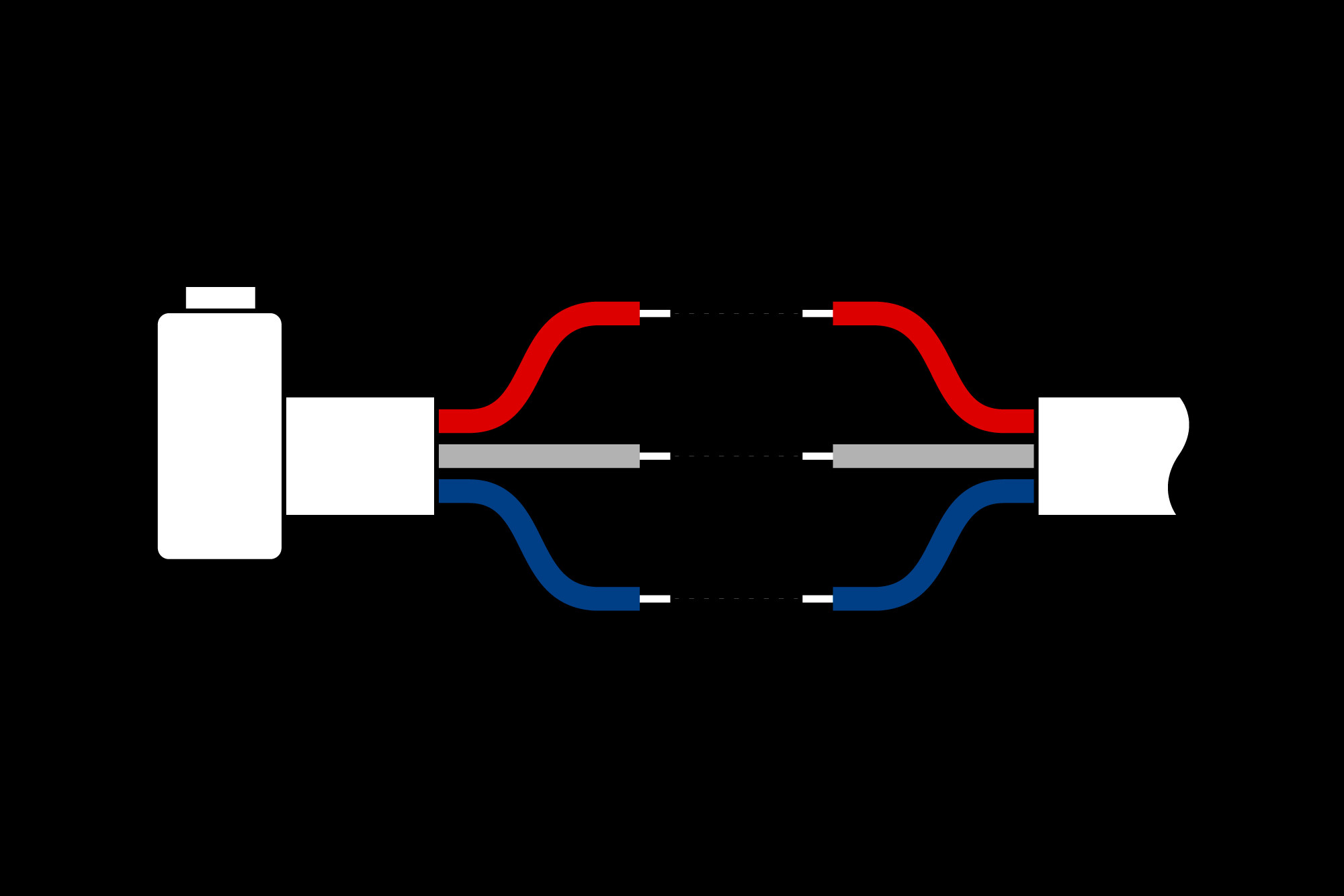
OEM sensor
Inductive sensors or proximity sensors on the transmission output
Most vehicle manufacturers use these. They are sensors with 3 connecting cables (+5 V or +12 V power supply, negative and signal), whose signal is usually compatible with motogadget instruments. The resistor previously used on the sensor is no longer necessary.
a = original speed sensor
b = +12 V
c = signal
d = mass/minus
e = to the vehicle electrical system and instrument
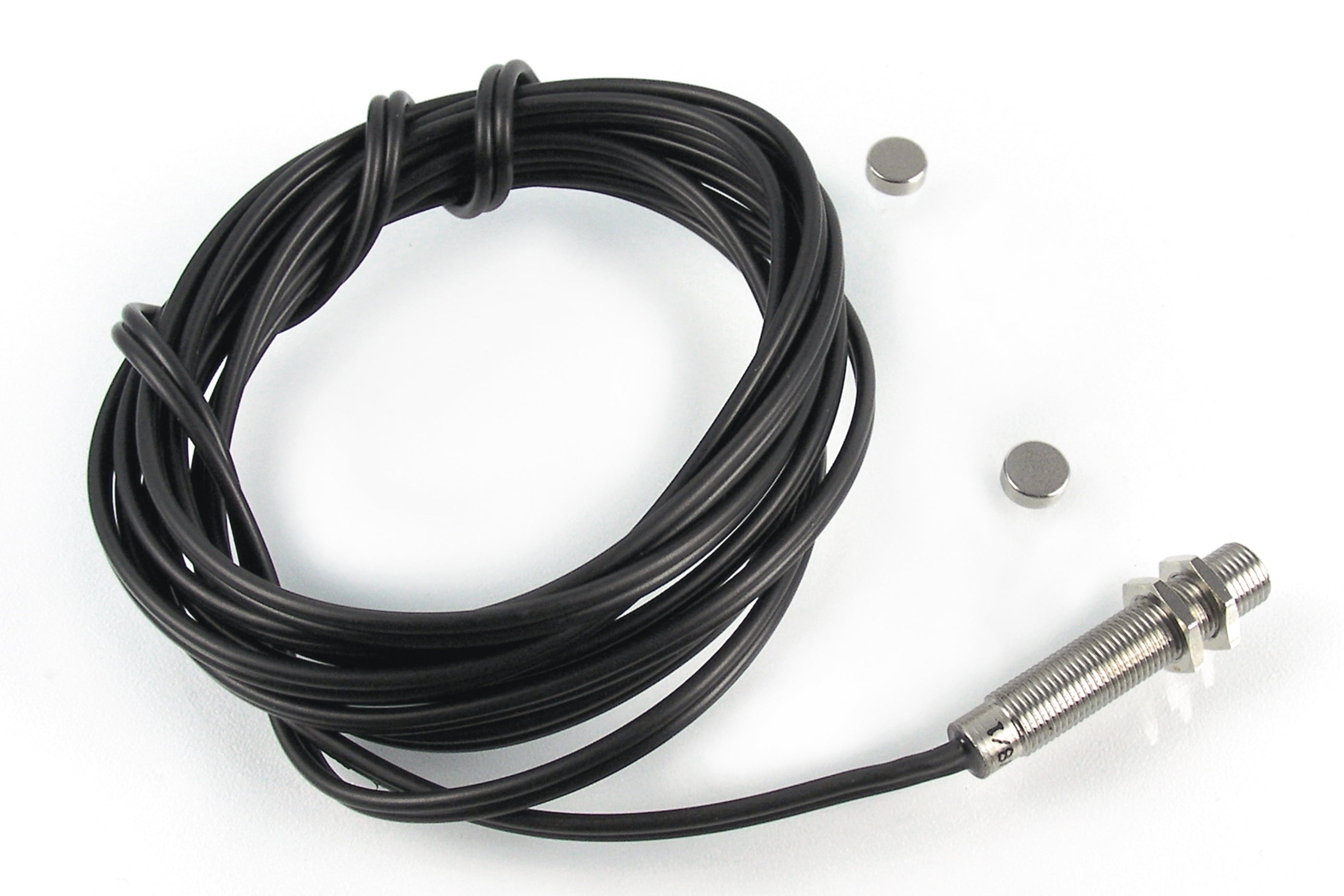
Reed sensor
Reed contact with magnet on wheel
This principle is familiar from electronic speedometers for bicycles, for example. The sensor always responds to one or more magnets located somewhere on the wheel. These sensors have 2 connecting cables. To enable them to be used for motogadget instruments, one cable must be connected to earth/negative; the other to the speedometer input.
Retrofitted or additional speed sensors
In older motorbikes, the speedometer is still driven mechanically by a cable. In this case – or if the original speed sensor is not compatible – the sensor included with the motogadget instrument must be used (which is a reed contact with magnet). The sensor can be fitted to the fork (with the magnet located on the front wheel). Or it can be installed on the swing arm or brake caliper mount (with the magnet located on the rear wheel/sprocket). The best place from a mechanical point of view depends on the bike. You may have to bend and install a small mount plate for the sensor. Choose a sufficiently sturdy fastener. The magnets can be glued to the wheel hub, brake disc mount, rear wheel sprocket, or the like, with two-component adhesive. The closer the magnet is positioned to the axle, the lower the centrifugal forces acting on it. Of course, it must be aligned exactly to the sensor tip, and the distance between the magnet and sensor must not exceed 4 mm.
Tachometer
The ignition pulse is normally used to measure and display the engine rpm. It must be compatible with the instrument. In principle, there are two different types of ignition signals or ignition systems:
Ignitions with negative input pulse
These include ignitions with mechanical ignition contacts (classic and vintage motorbikes), electronic analogue ignitions and electronic digital ignitions. The latter two are also called transistorised ignitions/battery ignitions. All electronic engine control units (ECUs) with combined injection/ignition are also transistorised ignitions. With this type of ignition, motogadget instruments can be connected directly to the ignition coil primary circuit (terminal 1, negative terminal). If the bike already has an electronic tachometer, or if the ignition/ECU has its own tachometer output, these may be used for connection. The only exceptions are bikes in which the ignition coils are integrated in the spark plug connectors and at the same time the original instruments are actuated via CAN bus. In this case, ignition signal pick-up could present problems.
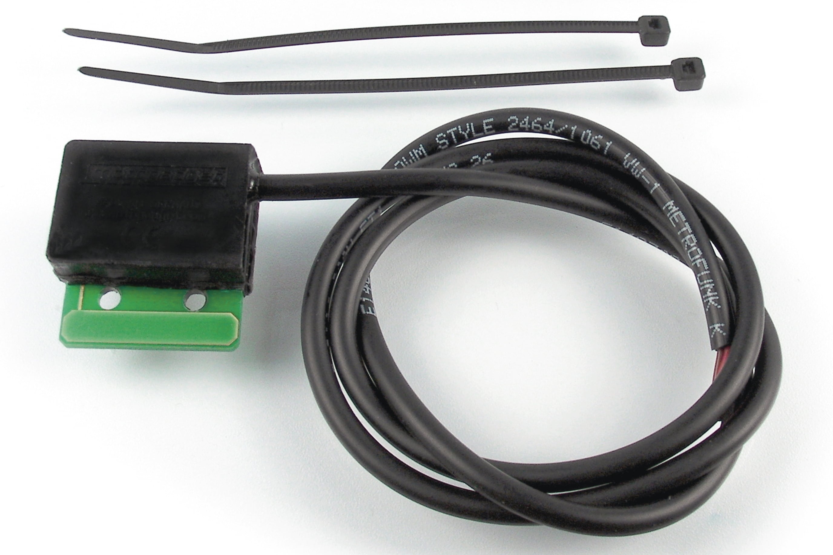
Ignition pick-up
Ignitions with positive input pulse
The capacitor discharge ignition (CDI), also called high-voltage ignition, is the only type in this category. This "self-excited" ignition does not need a battery and is often used in enduro bikes, single-cylinder machines and motorcycles with small engines. If your bike has this type of ignition, the ignition signal pick-up unit must be used.
Important: Some Japanese motorcycle manufacturers also refer to the electronic ignitions of street motorbikes described under a) with the acronym "CDI". This often causes confusion!
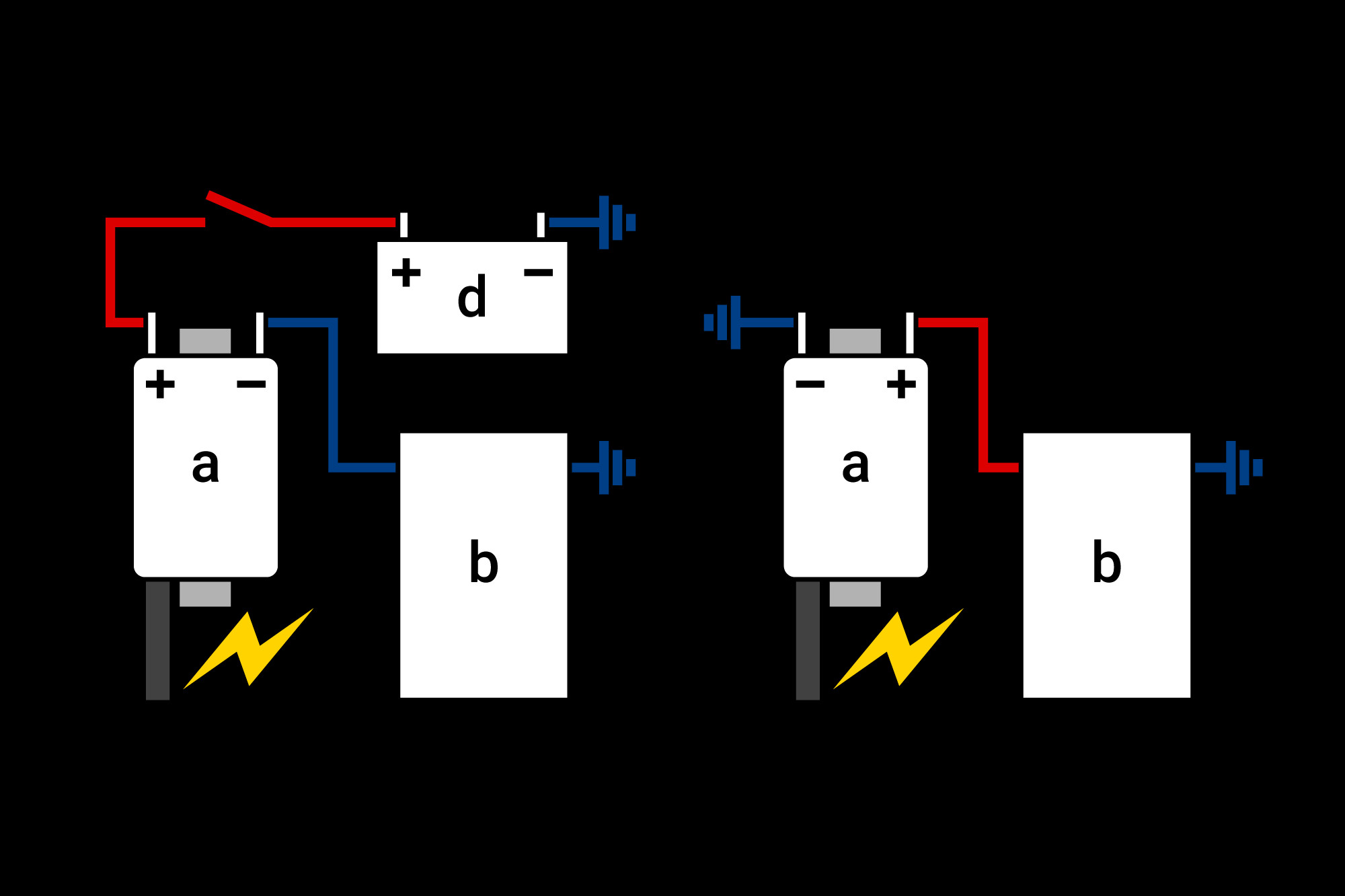
Transistor ignition (left), capacitor ignition (right)
Differentiating between the types of ignition
As a rough guide, most street bikes with multi-cylinder engines have a transistorised ignition, while single-cylinder machines – including those with larger engines – and small motorcycles often have a capacitor discharge ignition (CDI). You can tell reasonably easily by looking at how the ignition coil is connected. In the transistorised ignition, the switched positive of the electrical system is connected to one ignition coil terminal, while the other terminal is connected to the ignition unit (negative terminal). In the capacitor discharge ignition, one terminal is connected directly to earth/negative and the other terminal goes to the ignition unit (positive terminal).
Menu button
motogadget instruments are universal, and must therefore be calibrated and set on the motorbike. In addition, various measurements can be called up or reset on the display, using a small button supplied with the motogadget instrument. If you do not want to mount any additional buttons on your bike, you can use an existing headlight flasher button, for example, as long as it is negative-switched (de-energised).
a = ignition coil
b = ignition/ECU
c = ignition switch
d = battery
Wiring diagram
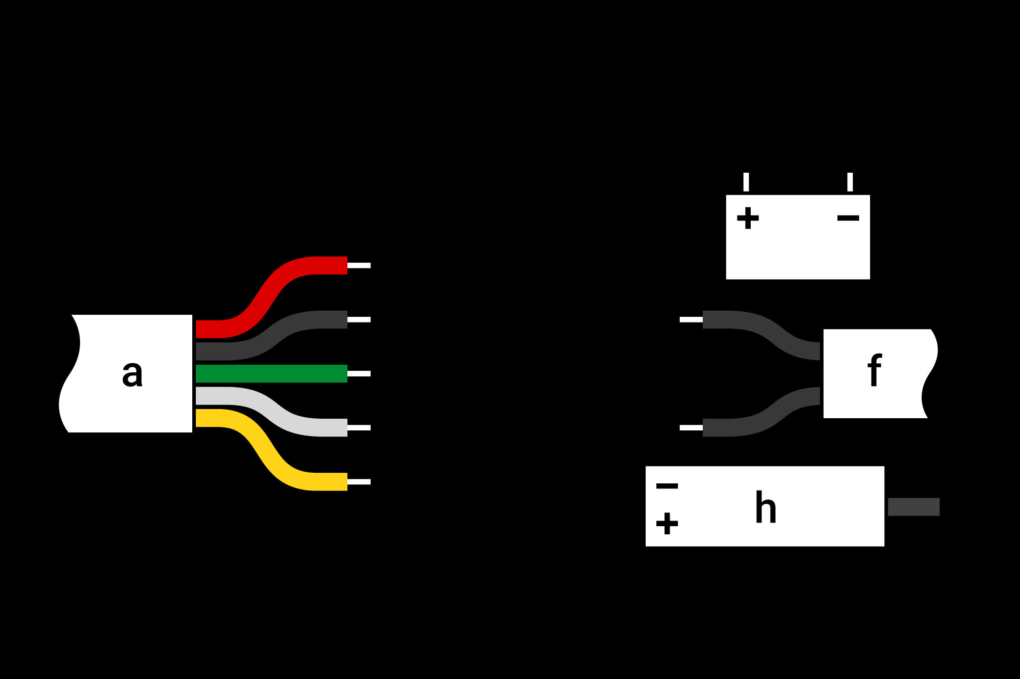
Wiring diagram of electrical connection: Example of motoscope mini
a = instrument
b = fuse
c = ignition switch
d = +12 V
e = button
f = reed contact
g = from ignition/ECU
h = ignition coil
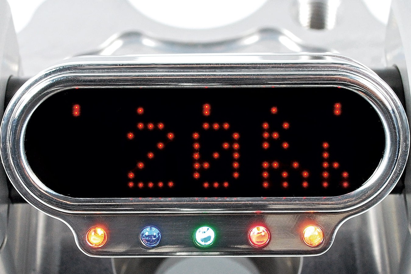
Final set-up
Once sensor and instrument have been securely fixed and all connections correctly made, you can reconnect the battery. Now enter the motorbike's specifications in Setup mode, and calibrate the speedometer. You can find detailed information on this in the instructions for use for the specific instrument.
The Louis Technical Centre
If you have a technical question about your motorbike, please contact our Technical Centre, where they have endless experience, reference books and contacts.
Please note!
These tips for DIY mechanics contain general recommendations that may not apply to all vehicles or all individual components. As local conditions may vary considerably, we are unable to guarantee the correctness of information in these tips for DIY mechanics.
Thank you for your understanding.


